Visit our webpage for Current Sensing Transformers (CT) to view standard models and learn more about our custom design capabilities.
A Current Transformer (CT) is used to measure or monitor the current in an AC power circuit.
The ratio of the primary current to the secondary current is a function of the turns ratio and the loss associated with the conversion. For example, copper losses in a voltage transformer affect the voltage regulation. In a current transformer, copper losses cause an increase in core loss, or a reduction in accuracy.
ISN2 = IPN1 – IMN1
Where:
ISN2 = the secondary current x the number of turns
IPN1 = primary current x the number of turns
IMN1 = ampere-turns required for core loss
The excitation current, (IM), determines the maximum accuracy that can be achieved with a current transformer. This current is defined as that portion of the primary current which satisfies the core losses. While the excitation current can never be eliminated, in some cases it can be compensated by adjusting the turns ratio.
If it were not for core losses, the primary and secondary currents would be exactly inversely proportional to the number of turns in the two windings. The error due to leakage flux is negligible in most current transformers using toroidal cores, and utilizing proper winding methods.
The total impedance of the devices connected to the secondary terminals (leads, meters, relay coil, resistance, etc.) of a current transformer is defined as its burden. Burden is expressed in volt-amperes (VA) or in ohms impedance.
Burden resistance should be kept as low as possible, since an increase in burden increases the core flux density (B) thereby increasing the core loss.
Utilizing Faraday’s Law:
B = 108 x IS(R + WR)4.44 x f x N2 x AC
Where:
IS = secondary current (amps)
R = burden (ohms)
WR = winding resistance
F = frequency (Hz)
N2 = turns
AC = cross section area (cm2)
B = flux density (Gauss)
The ratio-correction factor indicates the percentage amount that the secondary current value differs from the correct value.
The phase angle error is not applicable to current actuated devices but will affect the accuracy of devices that respond to the products, the sums or difference of currents.
Current transformer polarity can be defined by permanent markings (typically H1 – X1) or polarity dots.
Current transformers may have to carry very large currents in the event of short circuit, motor starting, etc. The windings heat very rapidly at a rate nearly proportional to the square of the current. Most of the heat will be stored in the copper. The short-time current limit is the time to raise the temperature of the winding to 105°C, considering ambient temperature.
The relationship of ration to turns is defined in the following formula:
Ka = (Kn + Nsa)/NP
Where:
Ka = new transformation ratio
Kn = nameplate ratio
Nsa = number of secondary turns added or subtracted
NP = number of primary turns
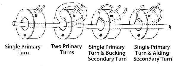
The following diagram represents various ways to adjust the turns ratio using primary and secondary turns.

For example, consider a current transformer with 1200:5 nameplate rating, with three primary bucking turns and two secondary bucking turns (passed through window so the generated flux is opposing):
Kn = 1200/5 = 240
Ka = (240-2)/3=79.3/1=396.66:5
Ka = 396.66 amps in primary provides 5 amps in secondary when configured per example.
Consider the two secondary turns passed through the window in the other direction (adding), in this case, the ratio obtained would be:
Ka= (240+2)/3= 80.66/1= 403.33:5
The secondary winding should always be loaded. If the secondary circuit is opened with primary current flowing, all the primary ampere-turns become magnetizing ampere-turns and usually will produce an excessively high secondary voltage across the open circuit.
Magnetization of the core, due to excessive fault currents or accidental open circuiting of the secondary, has the effect of increasing the ratio errors.
Our Sales Team is available to answer any questions that you may have. Contact them today to learn more!